AVF, Ray Tracing and Signal Attenuation
Originally Published inI have been a bit quieter in the Revit API discussion forum ↗ in the past day or two.
Why?
Well, I implemented a neat new little sample add-in, RvtFader ↗.
In a rather simplified manner, it calculates and displays signal attenuation caused by distance and obstacles, specifically walls.
That provided an opportunity for me to dive in again into two very interesting pieces of Revit API functionality:
- AVF, the Analysis Visualisation Framework, for displaying graphical data in a transient manner directly in the BIM.
- The
ReferenceIntersectorray tracing functionality to detect walls and other obstacles between two points.
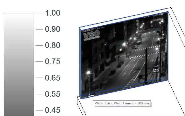
In the course of implementing the AVF part of things, I also resuscitated my trusty old RevitWebcam ↗ add-in.
RevitWebcam
RevitWebcam ↗ uses AVF and an external event to display a live webcam image on a selected element face.
The external event polls the webcam for updated images at regular intervals.
I now created a new GitHub repository to host this add-in and migrated it to Revit 2017.
Here it is displaying a webcam image on a wall:
Back to RvtFader, though:
RvtFader
RvtFader is a Revit C# .NET API add-in to calculate and display signal attenuation using the analysis visualisation framework AVF and ReferenceIntersector ray tracing.
![]()
Task
This application works in a Revit model with a floor plan containing walls.
It calculates the signal attenuation caused by distance and obstacles.
In the first iteration, the only obstacles taken into account are walls.
Two signal attenuation values in decibels are defined in the application settings:
- Attenuation per metre in air
- Attenuation by a wall
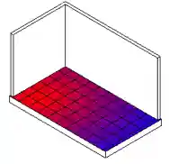
Given a source point, calculate the attenuation in a widening circle around it and display that as a heat map.
Implementation
To achieve this task, RvtFader implements the following:
- Manage settings to be edited and stored (signal loss in dB).
- Enable user to pick a source point on a floor.
- Determine the floor boundaries.
- Shoots rays from the picked point to an array of other target points covering the floor.
- Determine the obstacles encountered by the ray, specifically wall elements.
- Display a ‘heat map’, i.e. colour gradient, representing the signal loss caused by the distance and number of walls between the source and the target points.
Summary of the steps towards achieving this:
- Skeleton add-in using the Visual Studio Revit Add-In Wizards.
- External command for the settings user interface displaying a Windows form and storing data in JSON as developed for the HoloLens escape path waypoint JSON exporter:
- Display modal Windows form.
- Implement form validation using
ErrorProviderclass,ValidatingandValidatedevents. - Store add-in option settings in JSON using the
JavaScriptSerializerclass.
- AVF heat map, initially simply based on distance from the selected source point:
- Graphical debugging displaying model lines representing the
ReferenceIntersectorrays traced usingReferenceIntersector, conditionally compiled based on the pragma definitionDEBUG_GRAPHICAL:
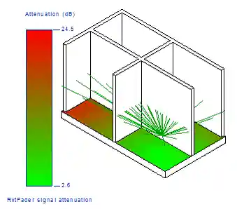
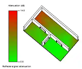
AttenuationCalculatortaking walls and door openings into account:
For more details on the implementation steps, please refer to the list of releases ↗ and commits ↗.
Further Reading
- The Analysis Visualisation Framework AVF:
- An introduction to AVF programming basics is provided by Matt Mason’s Autodesk University class CP5229 Seeing Data and More – The Analysis Visualization Framework ↗ (^)
- Discussion of AVF by The Building Coder
ReferenceIntersectorray tracing:- The
ReferenceIntersectorwas previously namedFindReferencesByDirection - Dimension walls using
FindReferencesByDirection - Intersect Solid Filter, AVF vs DirectShape Debugging
- Using
ReferenceIntersectorin linked files
- The
- Signal attenuation:
- Attenuation ↗
- Modelling Signal Attenuation in IEEE 802.11 Wireless LANs - Vol. 1 ↗
- The Basics of Signal Attenuation ↗
- RF Basics - Part 1 ↗ says “the free-space loss for 2.4 GHz at 100 meters from the transmitter is about 80 dB”.
Highlights
- External application with custom ribbon panel, custom tab, split button with main command and settings, always defaulting to main command.
- Settings storage in external JSON text file, displayed to user in Windows form, validated with detailed feedback.